When I bought my 1962 Alberg 35, Magic, in 2001, she was equipped with a pedestal-mounted wheel connected to the rudderstock with wire rope running over sheaves and a quadrant. The steering pedestal looked very yachty and provided a nice place for a cupholder, but I never really liked the arrangement. A boat of this size and hull type rarely needs a wheel’s extra leverage to turn its rudder, and I’ve always liked the responsiveness of a tiller. Also, at 6ft 5in and 230 pounds, I require a bit more maneuvering room than most, and the 32in destroyer wheel ate up a good chunk of the cockpit and made the companionway difficult to access.
Several years of ownership did nothing to change my mind, and after sailing on some much larger boats of similar vintage that were tiller-steered, I began to long for a tiller of my own. What finally drove me to the decision that I had to go back to a tiller was fear.
Over the seven years I had sailed Magic, there were several instances when I felt the wheel bind and freeze up while making a quick maneuver in a tight space. I was always able to solve the problem by turning the wheel in the opposite direction and then back again, but I was certain those close calls were a result of the wire rope riding up on one of the sheaves or quadrant and threatening to “jump.” To say it was not a good feeling is an understatement.
[advertisement]
Of course, this problem was most likely the result of deferred maintenance, but whoever had installed Magic’s steering quadrant and cables must have had a second career as a contortionist. No matter how hard I tried, I could not fit myself into the tight spaces under the cockpit to access the equipment.
I still could have lived with these problems if there had been an emergency tiller. Unfortunately, one of the previous owners had rebuilt the cockpit years before. In the process, he’d laid down a beautiful teak sole, but also cut about six inches off the top of the rudderstock and buried the remains beneath the cockpit with no access. So, knowing that somewhere, sometime, I could be faced with a situation where I had no control over the boat, I hatched a plan to install a tiller.
I eventually hauled the boat and spent several years of my spare time re-coring the decks and rebuilding a number of systems aboard. In the course of that work, I found that even though the lovely teak sole in the cockpit still looked great, the underlying deck was a rotten mess. As much as I liked the look and feel of the teak underfoot, I had to pull it up to fix the deck and decided this was the right time to convert the boat back to tiller steering.
After tearing out the steering pedestal and quadrant, I cut out the old cockpit sole and epoxied in a new end-grain balsa core with a single layer of 1708 biaxial fabric over all but a 2ft by 2ft area in the aft end of the cockpit where the tiller would be located. Now it was time to figure out the best design for the new tiller installation.
[advertisement]
I believe that when the boat was converted to wheel steering in the 1970s, the original rudder tube was cut and fitted with a stuffing box to accommodate the steering quadrant needed for the wheel. Over the years, that stuffing box, which was difficult to access, was a constant source of minor leaks. As a result, in my seemingly never-ending quest to remove holes in the boat below the waterline, this stuffing box seemed like a good candidate.
Looking at other boats, I found many designs with rudder tubes extended all the way up into the cockpit above the waterline. A bushing or bearing was usually located where the tube poked through the cockpit sole, so that even if a little water were to splash up that far, it would run harmlessly into the cockpit scuppers. I decided that this would be my best option and set to work.
Given that I would need to replace my rudderstock, I determined that the new stock would need to be 9in longer than the current one and then set to work dropping the rudder. As a first step I unbolted the strap that attached the rudder and stock to the keel and lifted it off the keel shoe. I then began the nerve-wracking process of digging a hole under the boat, only to discover there was a solid ledge about 6in underneath the keel that prevented me from digging any deeper. I ended up cutting the 1.5in stainless steel rudderstock with a Sawzall and many carbide blades, and sent the resulting pieces off to a machinist to fabricate a new one.
While this was being done I made the new rudder tube using a 2ft piece of structural fiberglass tubing with an inner diameter of 2in. As a first step I ground down the inside of the bottom with a small drum-sanding bit until the inner diameter was 2.5in. This allowed the new tube to fit nicely over the top of the existing rudder tube where it extended up from the bottom of the boat. After that I took a shorter 3in-long section of tubing and ground the inner diameter out to 2.5in and epoxied it in place over the existing tube to act as a collar and tie in the new section. I let that cure for a day or so before moving onto alignment.
Because the tolerances on the rudder stock are pretty tight, I needed to make sure the new rudder tube was perfectly aligned from the bottom of the keel all the way up into the cockpit. To do this I tied a string to the rudder heel on the keel and ran it up through the old tube (with the collar epoxied on) and through the new tube that fit over the old tube. This gave me a perfectly straight line from the bottom of the keel into the cockpit. Once everything was aligned, I epoxied the new tube onto the old tube and permanently mated it with the collar. Finally, I wrapped the entire joint in five layers of 9oz epoxy-impregnated cloth tape and let it all cure.
While waiting for the new rudder-tube joint to fully harden, I cut an angled 3in hole in a 12in square piece of half-inch structural fiberglass plate that would serve to connect the top of the rudder tube to the cockpit sole. I didn’t quite get the hole-saw angle correct, and the plate lay flat on the cockpit sole with the tube protruding through, so I used a round file to widen the hole until I got a perfect fit.
When I got the new 1.5in stainless steel rudderstock back from the machinist, I test fitted it, along with a bronze bushing, to make sure the stock was perfectly centered in the rudder tube before laminating the top plate to the tube and cockpit sole. Fortunately, all my measurements were correct, and the resulting assembly looked great. However, when I stepped back and looked at it from the cabin, something seemed off, and taking out a tape measure I found the center of the tube was off almost an entire inch to port. I rechecked all my measurements and checked to make sure the rudderstock rotated in the tube properly—it did. The only possible explanation was that the keel was out of line with the cockpit’s centerline.
A quick search online revealed this is not uncommon, and that many other Alberg 35s have the same problem. The good news was that while there wasn’t anything I could do about it (it was probably an issue with the original mold) it wouldn’t affect the operation of the rudder and any effect on performance was probably negligible. Basically, I had to accept it and move on. (After a full season with many people on board, nobody has noticed the problem other than me.).
[advertisement]
To tie it all together, I mixed up a batch of epoxy thickened with Aerosil and spread it out over the area of the cockpit sole I had left open for this project, as well as the bottom of the fiberglass plate. I then carefully slid the fiberglass plate over the rudder tube protruding into the cockpit and laid it down into the thickened epoxy on the sole. After that I used strips of edge-grain balsa to fill in the gaps around the plate and surrounding fiberglass. Finally, I wet out a square of 1708 biaxial fabric with a star-shaped hole cut in the center and laid it down so it adhered to both the fiberglass plate and the new rudder tube. I weighed it all down with sand bags to let it cure.
From this point on the job was a matter of laying down three more layers of 1708 biaxial fabric along with several layers of 9oz tape to make sure the tube was properly bonded to the new cockpit sole. After a few rounds of fairing compound and sanding, I was ready for paint. The final detail before painting was to install a retaining pin and set screw for the bronze bushing to keep the bushing from sliding down or rotating in the tube.
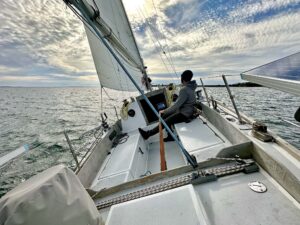
After a season of use, I can say without hesitation the project was a success. I love the direct feel of the tiller, and more importantly, I don’t have to worry about the steering failing anymore. The new cockpit sole is much stiffer than it used to be, due in part to the rudder tube being structurally bonded to the deck. Of course, as with any major boat project, it took much longer than I expected, but no part of this undertaking was beyond any boatowner who is familiar with basic tools and isn’t afraid to get a little dirty.
Photos by Matt Bowser
