

I had been sailing my Tayana 42, Eclipse, for a few years without any installed electronics on board. I’d gone pretty far up and down the New England and Mid-Atlantic coasts with paper charts, the Navionics app on my Android phone, a hand-bearing compass and the ship’s compass. However, last year I decided it was time to install a suite of electronics gear in order to make life underway safer, less stressful and more efficient.
I’m an experienced electronics installer, and I realize that the prospect of such a project can be daunting to a boat owner who has never attempted it before. Nonetheless, by following a logical sequence of steps, a reasonably competent DIYer should be able to install his or her own electronics. Therefore, what follows is a brief guide on how to go about it. Although I chose B&G instruments, the principles and techniques described here apply to any networked NMEA2000 (N2K) system.

Starting Out
*Make a plan. Before taking a single concrete step, I long thought and hard about the details of a foundational electronics system for Eclipse. As part of this process, I sorted my ideas into needs and wants, and then trimmed the list to fit my budget. For instance, radar and AIS didn’t make the list this time around.
From experience, I knew that if I focused on installing a proper network backbone with high-quality components, it would be easy to add to the system in the future. Build a strong foundation, think ahead, and it will pay off down the road in the form of huge savings of time and money.
*Do your research. Talk to your local marine electronics dealer before purchasing your gear. Having already settled on B&G equipment, I also spent a fair bit of time on the phone with tech support at B&G to make sure I wasn’t missing anything and that all the components were compatible. Communicating directly with the tech support is part of what you are paying for when you purchase new electronics. I learn something new every time I call.
*Due diligence. Unbox your gear and read the manuals. Approach the project slowly and with a solid understanding of how things work. To start out, I laid out the gear on my workbench and powered up a few of the components with a 12-volt power supply. It’s helpful to see things working together on the same table before it all gets spread out in the boat. If you’re unsure of the proper topology for your equipment’s NMEA (N2K) network, this is the time to figure it out. There are tons of resources online to help make sense of this stuff. If you are feeling overwhelmed, however, this is a good point to check with a pro. An experienced tech will have a much easier time helping you from the beginning, rather than trying to troubleshoot a problematic system after it has already been installed.
*Make a diagram. A whiteboard is great for this, but pencil and paper will do. I sketched out all of my cable routing and then took a picture of it. Computer flowchart tools like Microsoft Visio or Lucidchart (lucidchart.com) are also excellent tools. Having a printed diagram of the entire system will make any future troubleshooting much easier.
*Make a list. Many manufacturers include an NMEA 2k starter kit with their product bundles, but it’s often not enough. You’ll need primary wire for DC power, network cable, NMEA connectors, zip ties and mounts. You may also need terminal blocks, breakers, fuses, sealant and cable glands. Use your diagram! Count the number of N2K network T’s and estimate your required cable lengths. I invested in building my N2K network backbone from high-quality Maretron cables and connectors.
*Think about the physical installation. I chose to install my chartplotter in a swiveling NavPod and upgraded the steering pedestal guard tube to a larger diameter to accommodate thicker cables. Add everything to your running list and then—and only then—order your parts.

Mounting the gear
My installation involved the physical mounting of a number of transducers, displays and controls. Need to cut a hole to mount your plotter or your instrument displays? Don’t underestimate the time it takes to cut out a well-placed rectangle. Installing new through-hull transducers? Unless you have existing housings that are compatible with the new sensors, you’re going to need to haul out. Unless you go wireless, a new masthead transducer will also require pulling a serious length of cable down the rig. Take it slow. This is no weekend project. The good news? You’ve already made a plan, so stick with it!
I mounted my masthead transducer and ran the cable while I had the rig down. You can do this with the rig still up, but it’s more difficult. I also used the opportunity to rewire everything in the mast. Running wires is a real pain, and if I’m going to run one, I figure I’ll just pull all of them through at once. When pulling cables, always try to think ahead in order to save time later.
I consider the electronic compass a foundational component in the system, and it stayed on my must-have list. Manufacturers recommend finding a mounting location that is down low near the center of the boat and where magnetic interference is at a minimum. I stuck a handheld compass into various parts of my bilge and found the perfect place to mount my B&G Percision 9 (which provides not just magnetic heading, but also rate of turn, pitch and roll from its nine-axis sensor) at the centerline of the forward wall of the fiberglass holding tank. I used Weld-Mount (weldmountsystems.com) adhesive and stainless studs with nylock nuts for a permanent installation without holes.
Eclipse had been in the water for three years and was long overdue for a bottom job, so we combined that project with the installation of two new transducers: an Airmar DST 800 that provides depth, sea temperature and hull speed, and a ForwardScan mounted with a fairing block forward of the keel and near the centerline. This amazing device connects directly to the Vulcan 9 chartplotter to display a profile of the bottom in front of the boat.
I thought long and hard about where I wanted to mount my chartplotter, instruments and autopilot control. The two obvious locations were a dedicated space on the aft side of the sea hood and at the helm. Since the Vulcan offers built-in autopilot control of B&G autopilots, I made the decision to mount the more tactile autopilot control panel centered over the companionway. This would allow easy course adjustments while being in the best position to simultaneously control my main and genoa sheets. A pair of Triton 2 instruments were mounted on either side of the autopilot control on a custom-made mahogany panel.
The process of mounting the Vulcan 9 chartplotter at the helm proved a bit more involved than I expected. In addition to installing a new pedestal guard with a larger internal diameter for the passage of wires, I also had to drill larger holes in the cockpit sole to accept the fasteners and new wires. I mounted the pedestal guard feet with epoxy, but coated the bottom of the hardware with lip balm to make future removal less of a chore. The pedestal guard was drilled on one side to allow the wires to exit into the arm of the NavPod. This fully sealed approach offers weather protection for the gear while hiding all wiring for a more attractive install.
Running the Wires
Depending on how spread out your gear is, you may find yourself running cables behind joinery, through the bilge (avoid wet areas if you can) and above the headliner. Expect to open up parts of your boat you didn’t even know existed. No matter how many times I do this, it doesn’t ever get any easier.
Before you start pulling any cable, make sure you are ready to pull all of the cables from every origin to every destination. The key phrase here is “all of the cables.” This includes network cables, power cables, transducer cables and sonar cables. I started forward in the boat and worked my way aft, choosing to think about one section at a time. I outlined my workflow as follows:
1. Install zip tie mounts every 18in where you expect the bundle of wires to run. If I’m securing them to the hull side, I’ll use the composite style with high-strength Weld-Mount adhesive. Otherwise, I secure the small nylon type with stainless screws. Insert zip ties into each mount, but leave them unfastened.
2. Loosely trace a piece of scrap line through each newly established cable pathway. Tie a knot to mark the length of the wire run, then remove the line.
3. Check your diagram and make a list of every wire that needs to be run through this section of the boat. Are there any wires you may need for future things? What about a cabin fan or reading light? If it’s convenient, add it to the list!
4. Use your piece of line to measure and cut each wire from the spool. Create your bundle, even if it’s just two cables. I often use some electrical tape to wrap the bundle in a few places. The tape doesn’t snag and keeps everything together if you are fishing in really tight spaces or through conduit.
5. Pull your bundle through and secure it with the zip ties. This is often easier said than done. An extra set of hands can really help. Sweating and cursing is to be expected. Finally, use your diagonal cutters to cut your zip tie tails at a right angle so you don’t slice your fingers on them later!
6. Repeat this process until all of your wire is in place and hanging with extra slack at the termination points.
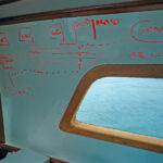
Planning is key
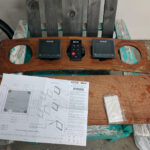
Planning the mounting panel for the instruments
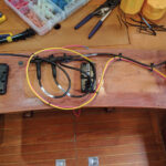
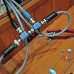
Connecting the network cables
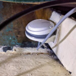
A good location for the compass
It’s more logical than it looks
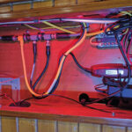
Try for a neat installation
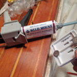
Weld-Mount adhesive is useful for these applications
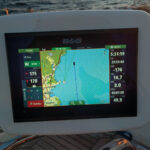
The plotter struts its stuff
Termination Time!
Terminating just means we’re installing connectors on the ends of all the cables. Follow your manufacturer’s directions for the DC power connections and always use an appropriately sized fuse on devices that call for it. If you used the network cables from a kit or bought pre-made cables, you’re in good shape. However, if you find yourself coiling up a bunch of unused cable and jamming it in the cabinet behind your electronics, you might want to consider trimming it to length and installing a field-attachable connector.
In my case, I used a mix of options for my N2K network connections. For the most part, I cut bulk Maretron Devicenet cable from a spool, then attached my own connectors. This method allowed for a clean installation with exact cable lengths.
Be warned that field-attachable connectors require a little practice and some finger acrobatics to assemble. It typically takes me about 15 minutes to make each one. Remember if you have pre-made cables that are too long that you can snip one end and put a field attachable connector on it while leaving the other in place, thereby avoiding the trouble of doing both ends.
Alas, the cable for the ForwardScan sonar was a bit more of a headache. It has a fat multi-pin connector on the end, and because it’s not a network device, it needs to plug directly into the sonar jack at the back the Vulcan chartplotter. Unfortunately, even with my larger-diameter pedestal guard, the connecter would not pass through. So instead, I acquired a manufacturer-specific sonar extension cable, clipped it in the middle and passed it into the pedestal guard. Then, with a mix of patience and heat shrink tubing, I carefully soldered each of the conductors back together and covered them in heat shrink while doing my best to maintain continuity through the foil shield by wrapping some scraps of the shiny mylar around everything. It was a chore, but everything came out OK. This would not have been an easy task for a novice.
Troubleshooting
Finally, the day of reckoning arrived, and I flipped on the breakers at the main DC panel after which my instruments and chartplotter fired right up. Nice! After that, I walked through the menus to set up my data sources, only to find that some of the sources were missing. Specifically, I had depth, speed and temp from the DST 800, but no wind or compass data—a tricky problem, since some sensors were working but others were not. I, therefore, began to think about all of those field connectors I’d put on. Had I made a mistake?
To solve the problem, late one night I clipped the end off yet another new N2K network cable, stripped each of the five wires inside down to its bare conductor, crimped on some fork terminals and attached each one to a separate post of a spare terminal block: all in an effort to make an NMEA 2000 network “breakout strip.” Using my digital multimeter, I then tested for adequate voltage across the red and black wires, were in each case I got 12.5 volts. In other words, that wasn’t the problem.
Next, I tested the resistance across the NET-Hi (white) and NET-Lo (blue) wires. It should’ve read 60 ohms, but I saw only 10. I was getting warmer. I unplugged the masthead transducer from the network and watched the resistance jump from 10 ohms to 120 ohms (the appropriate resistance when only one termination resistor is present). Clearly, the problem was at the top of the mast, where the transducer included a termination resistor since it also served as one end of the network backbone.
Armed with this day, some friends hauled me up the rig the following day, I brought down the problematic component and called B&G. They overnighted me the new part, and I installed it at 0400 just before shoving off for a trip to Maine. Everything worked, and life aboard Eclipse has never been better.
Basic topology of aN NMEA network
A basic NMEA network is comprised of a number of double-ended cordsets, tees, a 12v power supply cable and two termination resistors. Every device which connects to the network is connected to the network “backbone” with a tee and a dedicated “drop cable.” Power is supplied to the network with a special power supply cable which connects with a tee to the backbone. Finally, a termination resistor is required to be plugged into the backbone at either end.
NMEA 2000 networks use technology that was developed for the electronic controls in automobiles. A properly designed and installed N2K network will provide a very robust foundation for the intercommunication of your ship systems.
Boat systems specialist Phil Gutowski lives on his Tayana 42, Eclipse, in Boston and cruises the New England and mid-Atlantic coasts.
Photos by Phil Gutowski
April 2018


")


